1. Go to Ground Floor Plan, place a camera face on to the plane you want to cut
2. When the camera view opens, tick 'section box'
3. Click on the section box boundary to activate the grab handles and open the floor plan view again - section box lines should still be highlighted for you to move (if not, go back to camera view etc)
For later versions of Revit, see this tutorial: http://www.youtube.com/watch?v=oaRcLLXsOq0
Wednesday, October 22, 2014
Thursday, March 27, 2014
Linking Files
Linking other Revit files
eg. electrical services etc.Open a 3D view in the main file so you easily see what's going on with the position of the linked file, if needed. (Note: if 'Link Revit' is greyed out, this should also fix that).
1. Insert menu, 'Link Revit'
2. Navigate to the place where the other revit files are. IMPORTANT - all the files to be linked, including the main file, must be in the same folder/place.
3. Select the file and choose to link as below, with positioning using 'Auto - by shared coordinates' (this assumes you are all using the correct coordinates)
Saturday, October 12, 2013
Sheets - Splitting Schedules over more than one Sheet
When you have a really large schedule, the only way to split between sheets is to filter the schedule and copy, but there is a trick to copying (dont use 'Duplicate') so see the link below to a video..
Basically involves:
http://blogs.rand.com/architectural/2011/04/splitting-a-schedule-across-sheets-in-revit.html
Basically involves:
- filter the schedule so it fits on a page (eg. by room number or door ID etc)
- rename appropriately
- right click on the selected schedule in the project browser (not in the view screen)
- copy to clipboard
- open up any other view (doesn't matter what, just can't be a schedule view) and paste - the copied schedule will paste here (but wont'affect the view you opened)
- then use the filter to adjust the final schedule size of teh copied schedule, rename it appropriately
http://blogs.rand.com/architectural/2011/04/splitting-a-schedule-across-sheets-in-revit.html
Thursday, October 3, 2013
Walkthroughs
= a camera that follows a path that you define; the path comprises frames and key frames.
*Key frame = a modifiable frame where you can change the direction and position of the camera. Each click results in a key frame.
By default, walkthroughs are created as a series of perspective views (but can also create as orthographic 3D views).
As you edit a walkthrough path, you may want to see the results of your changes on the actual view. To open the walkthrough view, click Modify | Cameras
Walkthrough
(Open Walkthrough).
see also http://www.youtube.com/watch?v=pGZmtRoXzjM
OR JUST DONT RENDER...perhaps just have a nice render for the final image or the very first one...
Read more: http://www.ehow.com/how_8590258_create-walkthrough-revit.html#ixzz2gcE03nUK
http://whatrevitwants.blogspot.co.nz/2010/02/how-to-create-revit-walkthrough-and.html
https://www.youtube.com/watch?v=ijfjldYSqYg
https://www.youtube.com/watch?v=yrcdKOG7ti8 - making horizontal modifications (eg. the path)
https://www.youtube.com/watch?v=fyaSMF0bkEQ - making modifications in elevation (ie. easier way to visualise the heights of the camera particularly if using stairs)
https://www.youtube.com/watch?v=P_SSihizZ4U - more vertical modifications, using a different elevation view
https://www.youtube.com/watch?v=WfkEOI7QuR0 - some more editing, rendering
https://www.youtube.com/watch?v=_ynbo7j0i-8 - extending the path
*Key frame = a modifiable frame where you can change the direction and position of the camera. Each click results in a key frame.
By default, walkthroughs are created as a series of perspective views (but can also create as orthographic 3D views).
- Open a view in which to place the walkthrough path (usually a floor plan but can also make in 3D, elevation and section views).
- View
Create
3D
(Walkthrough).
- [If wanting an orthogonal 3D view instead of perspective, clear the Perspective option on the Options Bar, and select a view scale.
- If in plan view, can vary camera height by offsetting it from a selected level (can give effect of camera is going up/down a flight of stairs).
- Place the cursor in a view, and click to place a key frame*.
- Move the cursor in the desired direction to draw the path.
- Click again to place another key frame.
- You can place key frames anywhere, but you cannot change their position during creation of the path.
- You can edit the key frames after you finish the path.
- To finish the walkthrough path, you can do any of the following:
- Click Finish Walkthrough.
- Double-click
- Esc.
Editing a Path
- Similar to editing perspectives - Project Browser, right-click the walkthrough view name, and select Show Camera.
- To move the entire walkthrough path, drag the path to the desired location.
- To edit the path: Modify | Cameras tab
Walkthrough panel
(Edit Walkthrough).
- For Controls, select Active Camera.
- Drag the camera along the path to the desired frame or key frame. The camera snaps to key frames. (Or type the frame number in the Frame text box).
- While the camera is active and located at a key frame, you can drag the target point of the camera and the far clip plane.
- For Controls, select Path. The key frames become controls along the path.
- Drag a key frame to the desired location. Notice that the value in the Frame text box stays constant.
- For Controls, select Add Key Frame or Remove Key Frame.
- Place the cursor along the path, and click to add/remove a key frame.
As you edit a walkthrough path, you may want to see the results of your changes on the actual view. To open the walkthrough view, click Modify | Cameras
Editing Frames
- Open the walkthrough
- Modify | Cameras
Walkthrough
(Edit Walkthrough).
- Options Bar, click Walkthrough frame edit button
.
- The Walkthrough Frames dialog has 5 columns that show the frame properties:
- Key Frame column - total number of key frames in the path. Click a key frame number to display where that key frame appears on the walkthrough path. A camera icon displays at the selected key frame.
- Frame column - the frame at which the key frame displays.
- Accelerator column - numerical controls for changing the speed of the walkthrough playback at a specific key frame.
- By default, there is a uniform speed at which the camera travels along the entire walkthrough path. You can change the speed by increasing or decreasing the total number of frames or by increasing or decreasing the number of frames per second. Enter the desired value for either
- To change the accelerator value for key frames, clear the Uniform Speed check box, and enter a value for the desired key frame in the Accelerator column. Valid values for the Accelerator are between 0.1 and 10.
- Speed column - speed at which the camera travels along the path at each key frame.
- Elapsed Time - the amount of time that has elapsed since the first key frame.
To help you visualize the distribution of frames along the walkthrough path, select Indicators. Enter a value for the increment at which you want to see camera indicators.
You can move the position of the camera's target point at a key frame, for example, to create the effect that the camera is looking side to side. To reset the target points back to following the path, click Modify | Cameras
Walkthrough 
(Reset Cameras).
see also http://www.youtube.com/watch?v=pGZmtRoXzjM
Exporting
You can export to an AVI or image file. When you export a walkthrough to an image file, each frame of the walkthrough is saved as an individual file. You can export all frames or a range of frames.- Open the walkthrough view.
- Click
Export
Images and Animations
Walkthrough. The Length/Format dialog opens.
- Under Output Length, specify:
- All frames to include all frames in the output file(s).
- Frame range to export only a specific range of frames. For this option, enter the frame range in the entry boxes.
- Frames/second. As you change the number of frames per second, the total time automatically updates.
- Under Format, specify Visual Style, Dimensions and Zoom to the desired values.
- OK.
- Accept the default output file name and path, or enter a new name.
- Select the file type, either AVI or an image file (JPEG, TIFF, BMP, or PNG).
- Save.
- In the Video Compression dialog, choose a video compressor from the list of compressors you have installed on your computer.
- To stop recording the AVI file, click Cancel next to the progress indicator at the bottom of the screen or press Esc.
Rendering...
It is better to render the images, or individual frames of the walk-through, out to a JPEG or TIFF format.
Then use video-editing software to put all of the frames together into a video format. The human eye sees up to 30 frames per second; therefore, you should set your walkthrough's frame rate to 30 frames per second. This means a one-minute walkthrough will contain 1,800 still frame images.
If you render the walkthrough direct to a MPEG, AVI or other video format, you run the risk of the walkthrough getting an error before the walkthrough video finishes rendering. If this happens, the rendered walkthrough video will be corrupt and will not play.
OR JUST DONT RENDER...perhaps just have a nice render for the final image or the very first one...
Read more: http://www.ehow.com/how_8590258_create-walkthrough-revit.html#ixzz2gcE03nUK
http://whatrevitwants.blogspot.co.nz/2010/02/how-to-create-revit-walkthrough-and.html
https://www.youtube.com/watch?v=ijfjldYSqYg
https://www.youtube.com/watch?v=yrcdKOG7ti8 - making horizontal modifications (eg. the path)
https://www.youtube.com/watch?v=fyaSMF0bkEQ - making modifications in elevation (ie. easier way to visualise the heights of the camera particularly if using stairs)
https://www.youtube.com/watch?v=P_SSihizZ4U - more vertical modifications, using a different elevation view
https://www.youtube.com/watch?v=WfkEOI7QuR0 - some more editing, rendering
https://www.youtube.com/watch?v=_ynbo7j0i-8 - extending the path
Wednesday, May 29, 2013
Lighting for renders
Use studio lights for a light source with no fittings.
If rendering in sunlight then will need the source to be around 3 times stronger than sunlight eg. 20,000W
If wanting a night shot, choose only artificial lighting in GD window.
Studio lights - wanting a strong light use 10,000W (indirect only).
If rendering in sunlight then will need the source to be around 3 times stronger than sunlight eg. 20,000W
If wanting a night shot, choose only artificial lighting in GD window.
Studio lights - wanting a strong light use 10,000W (indirect only).
Tuesday, January 22, 2013
Central files, local files
Creating a Central File for worksharing/synchronising
1. Open the file you want to make the 'central file', click 'save as'
2. Choose the desired central location and file name, then under 'options' in the save window check the 'Make this a central file after save' option.
This is now the central file in the location you selected.
Creating a Local Copy
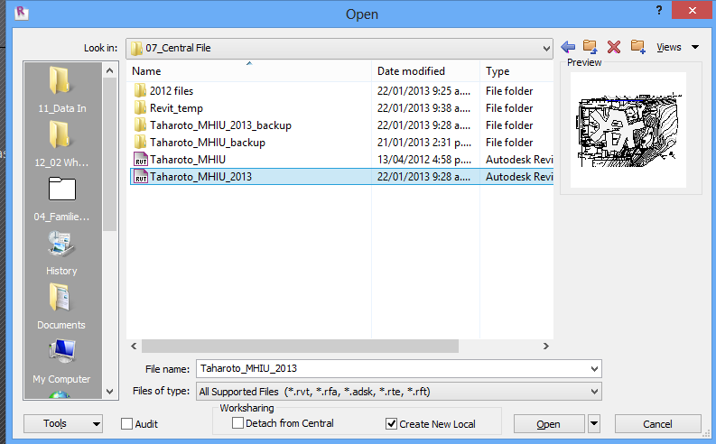
Everyone working on this project then wants to create their own local copies they can work on, and synchronise to the central file at regular intervals. (NB. all users must have access to the central file location for this to work).1. To make a local copy, open the central file by going via the Revit Projects, Open function.
2. Select the newly created central file.
3. There should be an option at the bottom of this window next to open which is automatically checked to 'Create new local'
4. Click 'Open'.
A new local copy has now been created on your computer (in your default directory for saves) and any automated or default save actions will now save this file there instead of back to the central file- but the system will also prompt you to synchronise at regular intervals with the Central file (you can choose to synchronise with the Central when needed as well).
Thursday, May 24, 2012
Curtain walls & glazing
Curtain walls - editing
- Project Browser menu (rhs)
- Curtain Panels (right down the bottom) - System Panels - make a copy and edit (need to double click)
- To edit peices of a curtain wall/roof, need to make sure you've added in some grid lines first to create a section, then click on that panel, and 'unpin' to edit the properties of that section...
- To place a curtain wall door:
- make the size by making a panel of this size first (grids), though can adjust later but less potential for problems if you set the grids up first...
- select the panel only (have to use the TAB key otherwise will prob select the whole curtain wall), unlock - default will be locked
- then go to properties and select the door for this (will be found under the curtain wall glazing panels area, not in 'doors') (or sash window)
- The door (or window) will be as large as the panel ie. will expand or shrink to fit. To resize the door, you must resize the panel space instead.
- NB. the default appears to be for double glazing (2 panes of glass) - this appears in the materials editor area (appearance)
Wednesday, May 23, 2012
Crazy shapes - conceptual masses
File new - Conceptual Mass - Metric Mass
Set up your reference planes and levels
eg. for my media 'wall':
Set up your reference planes and levels
eg. for my media 'wall':
- Floor plan, start at level 1, draw a crazy line (bottom)
- Move to level 2, draw the other line (top)
- Select the 2 lines
- Create Form
- Load into project...
- Massing, Place Mass, select the one you've just created
Wednesday, May 16, 2012
Creating files for 3D printing or CNC!
3D Printing from Revit files
Need: Revit + STL plugin + Rhino (just to scale correctly)
1. Need plugin for STL exporting (free download from Autodesk site)
2. Make sure the model is 'watertight' and the walls will be at least 3mm (so for a 1:200 scale, a minimum of 600mm thick!). Make sure model is hollow so it doesn't cost too much (for 3D printing, otherwise don't worry)
3. Make sure you have the 3D view open in Revit and the scale you want exported (eg. 1:200)
3. Export as STL file (add-in menu item in Revit window)
4. NB. This exports your model in weird units (perhaps feet??) so have to open up the STL file created from Revit in Rhino (easiest option but probably could use 3dsmax), then scale:
Scaling in Rhino
- draw a line of a face you know the measurement for, as it should be, when scaled eg. 108.85mm (line, enter, draw line using shift key to keep straight, type in the unit before you click the final point, click enter)
- line up the model with this line (select, move using right mouse held down)
- select model
- click scale icon (or type in scale, enter)
- click on first origin point of the side you are measuring, then the second, then the end of the new line you have drawn to the scale you need - this should scale it to the correct size
- save as STL file
- hey presto you now have a correctly scaled file ready for 3D printing! :)
CNC machine for typography
- Follow the revit steps as per above, for just the typography but don't need to worry about thicknesses of anything.
- Export as a DXF file - if using Rhino at uni, make sure the version is older eg 2007
- Open Rhino, open the file and the steps as above for scaling
- Save as the default Rhino file type and send to the CNC machine as is.
Monday, April 16, 2012
Families - things to determine before creating
- Hosted versus non-hosted - generally most things are non-hosted but note the following:
- if it needs to create an opening in its host (eg. window) be certain that you'll only be doing this with one kind of host as a hosted element can only cut one type of host. For example, a window created this way can only cut eg. a wall OR a ceiling, not both.
- if you're not sure of the above, but want it to move with a wall etc, then place the element and select the 'Moves with Nearby Elements' option so when the host moves, so does the placed element.
- another option is to make the element 'face-based' or nested
- Family category - critical to choose the correct one
- Insertion point - determines the location about which the family will geometrically flex;
- important if you expand eg. a table later to fit more chairs - you'd want the insertion point to be in the middle of the face of the table in that case
- the reference level in the Family Editor corresponds to the datum level in your project so determines the visibility of your component in different views
- if you swap this component with another, if the insertion points are the same then its all good...
- Flexibility - if you're sure you'll need to modify some of the dimensions later when in use, then create some rules first:
- reference planes are the simplest way to add rules - they do not have endpoints so are used to create linear geometric relationships
- reference lines do have endpoints so can be used to control angular relationships
Tuesday, April 10, 2012
In-Place components
Similar concept to massing - like a family massing
For large odd things (not normal stuff) so don't use when in conventional projects
You can only apply materials for in place families when you are in edit mode.
NB. have to make sure masses are visible in view (VV)
Differences:
Step One: create a face
For large odd things (not normal stuff) so don't use when in conventional projects
You can only apply materials for in place families when you are in edit mode.
NB. have to make sure masses are visible in view (VV)
- Component - Model In-Place
- When the option window appears, select 'Mass'
Differences:
- model lines for creating forms unlikely to require further iteration or rule-based parameterisation
- reference lines if you think you'll be using formula or other rules, they allow for more flexibility, best to use reference lines regardless
Step One: create a face
- Massing & Site - In-place mass - Reference Lines - draw a shape eg. use the spline line:
- go to the 3D view and click 'top' on the view cube so you're looking down
- draw the line you want, (make sure it's defaulting to creating this on level 1 - check in the options bar)
- then draw another line this time on level 3 (change this in the options bar)
- select both lines and Create Form
- Finish Mass (will get error but this is okay)
- Create a wall:
- select this face
- Home - Wall by Face, click away and a wall will have been created from your shape!
- Select the mass - easier to do this if you disable the wall visibility (VV)
- Edit In-Place - you can move the control points.
- Finish Mass
- Unhide the wall and select
- click Update to Face
Rendering
NB. Screen print is for quick rendering
Setup - Camera - Crop Size (ie. no scale)
Width A3 (usually) = 380m but make slightly bigger eg. 500mm and "lock scale" and then shrink down to size on the sheet to make the image crisper.
View - Render - Background - Style - Image
Settings
Export, image,
Setup - Camera - Crop Size (ie. no scale)
Width A3 (usually) = 380m but make slightly bigger eg. 500mm and "lock scale" and then shrink down to size on the sheet to make the image crisper.
View - Render - Background - Style - Image
Settings
- Render - Adjust Exposure - white point, take this to 5, saturation - 1:36
- Set up the camera first (Setup), in plan view
- reflections - eg. for windows, tip is to create a wall with a photo of what you want reflected and set the camera at a 45 degree angle to this so is reflected in the window...best if the sun is behind the camera
- Background gradient
- Shadow - ambient
- Sun intensity - 70
- Ambient light - 30
- Don't go lower than 150 DPI for final printing
- Studio lights - these have no structures associated so are used for pure light source
- if rendering in daylight with lights, need the light to be very bright eg. 3x stronger than sunlight (20000W)
- if wanting a night render, use 'artificial lighting' only
- put soft lights inside...can group lights to apply same properties to a whole group, or turn a whole group off and on
Export, image,
- zoom = 100%
- shaded views, jpeg (lossless), 300 DPI or more
Sunday, March 4, 2012
Massing
This is for concept models, basic shapes (which you can fill in later)
- Set up some elevations (floor levels) first
- "In Place Mass"
- In Place Mass tool
- Give the mass a name (eg. Building 1 etc) which will then take you into Sketch mode
- Create a form eg. solid, then keep modelling then...
- Creat floors - select the model, the Mass Floors tool will appear on far left, select the floors you want to create (determined by the elevations you previously set up) - this will create the levels.
- Go back to Massing & Site menu and create the roof, walls, floor etc (ie. this will now create the thickness, solid components)
Tuesday, February 28, 2012
Topography
NB. if you have contour map already:
Massing & Site - menu options.
Topography - NB. can only work with this when in the 'site' view (project browser).
Contour lines - click on existing ones (or just the outside line if that's all you have so far), and a menu option 'Edit Surface' will appear, click on this, then add the correct elevation for the new contour line and 'Add point' along the contour lines.
To make contour lines visible, can change this by clicking on the Model Site menu option and adjusting the 'At Intervals of' distance. eg. change to 500mm or 250mm or 5000mm etc. whatever your contour lines are at.
NB. when placing building, make the topography offset down by around 300mm (offset -300) to create appropriate step up to building pad/floors (make ground lower than building, not in line with)
Building pad
This is like an excavation tool - with shear sides...
This is the more common way to create a building site.
Subregions = for different materials on the typography such as driveways, lake, pool, parking etc.
Labelling contour dimensions
eg. parking components, etc
NB. Site, place when in site view (eg. not ground level) and these will follow the contours
Retaining wall/embankments
Place a wall, Create a section
Move contour points onto the line of the wall, edit the contours, click on 'add point'
- Insert, Image - will place the image behind so you can trace the lines.
- Anything 2D can be scaled - so pick something on the image you know the dimension of and use the Scale Tool (modify, 2 squares icon).
Massing & Site - menu options.
Topography - NB. can only work with this when in the 'site' view (project browser).
- Toposurface tool, Points - the elevation of each will be shown in the options bar where you can change this, that is, change the elevation and trace over contour lines
- Topography = 'existing' phase (see below about phasing). That is, the topography exists at the start, you will be 'rennovating' it.
- So, you'll need to change your site to 'existing' phase in the Properties, Phase area.
Contour lines - click on existing ones (or just the outside line if that's all you have so far), and a menu option 'Edit Surface' will appear, click on this, then add the correct elevation for the new contour line and 'Add point' along the contour lines.
To make contour lines visible, can change this by clicking on the Model Site menu option and adjusting the 'At Intervals of' distance. eg. change to 500mm or 250mm or 5000mm etc. whatever your contour lines are at.
NB. when placing building, make the topography offset down by around 300mm (offset -300) to create appropriate step up to building pad/floors (make ground lower than building, not in line with)
Building pad
This is like an excavation tool - with shear sides...
- Building pad tool. Draw your pad, tick.
- This takes means of elevations and creates a pad at the best height.
- massing or
- quickly flatten something or
- when you have a basement.
This is the more common way to create a building site.
- Tool = Graded Region, when you choose this, Revit will ask a question, select the second option (create a new toposurface based on the perimeter points only)
- Then click on the topography to activate the place point tool, change the elevation points to what you want (options bar)
- NB. select wireframe view to see where you are going
- Now change phase filter to 'show complete'
- If you create a section now, it will show 2 phases, the existing (dotted line) and the new graded line (solid)
- So you don't want to see the extra hatching which is the old typography but still want to show where the existing topography went:
- Detail lines - (NB anything in this section is view-specific only)
- Annotate, Detail Line (or DL for short), select line style = hidden line (dashed), and trace over the existing phase line
- Then filder the phase to 'Show Complete'
Subregions = for different materials on the typography such as driveways, lake, pool, parking etc.
Labelling contour dimensions
- Massing & Site
- Label contours
- Click on one side (like you're going to make a section line) and then the other and the labels will be added automatically along that line (this line is only shown temporarily while you're in this mode)...
eg. parking components, etc
NB. Site, place when in site view (eg. not ground level) and these will follow the contours
Retaining wall/embankments
Place a wall, Create a section
Move contour points onto the line of the wall, edit the contours, click on 'add point'
- NB. The Fourth Dimension (time)
- phasing - new, existing (property) and can filter these eg. for rennovations
- so for typography you use the 'existing' phase then change it so final will be seen only when filtering to 'show complete'. Therefore, change site to 'existing' when starting off (Properties, Phase area)
- Demolish tool
- This is in the Manage tool options...NB. will only work on walls change to 'existing' phase.
- nb. to clean up, drag ends of lines don't use the trim tool, with Demolish.
Thursday, February 23, 2012
Symbol
Create a new symbol:
- File, New, Family, Annotations, Generic Annotations - (use Metric Profile to create a 2D component that uses a scale, do not use the annotations templates for scale components)
- draw something,
Families - hosted components
That is, things that require a wall/door etc like a window component.
New Window
New, Family, Metric Window template
This template is basically an opening in a wall which you manipulate
First you change the opening (only if you want to change it):
Below are steps to create one-off components you can change on the fly with handles
Instance parameters - components
Select the dimension, (eg. in an elevation view) and check the 'instance parameter' in the options bar
NB. test this using the 'blue box' icon (family types icon) to change the width and height - see test window example in my project
New Window
New, Family, Metric Window template
This template is basically an opening in a wall which you manipulate
First you change the opening (only if you want to change it):
- select the opening, Edit sketch, sketch shape of new window opening
- create reference planes for the outside and inside of the frames if you are going to change the dimensions at all in the future (even if you're not, it's easier this way) - that is, you can then lock the reference planes so the frame thickness remains even if you make the opening bigger/smaller
- use the offset function - pick tool, then alter the offset distance, pick the opening...etc...
- remember to label the dimensions: Annotate, Aligned dimenion, then while this is still active, go to the properties and add a label (eg. Width, Height etc).
- extrusion, set plane (pick a plane, centre line),
- pick lines tool, trace opening then pick lines tool again and then set offset for frame thickness
- extrusion properties = start 50, finish -50
- materials, click on the formula icon, add parameter, give it a name you can easily find (eg. materials - frame)
- properties, identity data, subcategory, choose 'frame/mullion' so Revit knows what it is
- click done
- extrusion, pick lines tool, trace inside opening
- extrusion properties = start 5, finish -5 (or whatever you want for glass thickness, this will give 10mm)
- this time, for materials, just choose the default glass setting rather than steps above
- properties, identity data, subcategory, choose 'glass' so Revit knows what it is
- click done
Below are steps to create one-off components you can change on the fly with handles
Instance parameters - components
Select the dimension, (eg. in an elevation view) and check the 'instance parameter' in the options bar
NB. test this using the 'blue box' icon (family types icon) to change the width and height - see test window example in my project
Sunday, February 19, 2012
Materials & Colours
Any material opened for editing will always open/go to the global materials settings (ie. regardless of how you arrive at this area), so will change materials globally for that component selection.
That is, eg.
- select component
- edit type (properties)
- eg. structure, materials - click on the ... which will bring up the materials editor for global changes
1. always Duplicate when modifying (the duplicate icon)
2. Stick to Revit naming conventions so it's easy to find
Appearance = for rendering
Graphics = appearance in Revit, (SD on keyboard), always check the 'use render appearance for shading'
Two ways of applying
1. Edit parameter - Edit Type in properties, etc (above) and all of this same type will change
2. Instance parameter - if you just want that instance of the component to change (eg. just one face):
- modify, paint, choose a colour, then click on the component
- don't click DONE until you've finished changing materials
- probably how I'd do this for concept models
1. Open the model, select the (eg) table top. (easier to do this in plan view)
2. Go to properties, Material, click on the formula button not the 'By Category' window there...this will open up an "associate family parameter" window. Add parameter, name it something sensible like 'materials - table top', leave 'Type' selected, Ok.
The steps above will allow you to change the materials when using this model in Revit.
1. Open the model, use the 'blue box' icon to create new types within this family editor.
Probably only want to do this for standard things like glass.
Paint Bucket (PT)
NB. rule of thumb = don't change colours on exterior corners.
Generic Annotations, Text
Text = normal text functions
Text (label) = quite different, imports a label, the size of a label (when creating a new one) is important as it must be able to accomodate likely changes to the text - ie this will change as you change parameters
Generic annotations
Text - can set up a new family template for standard notes (eg. standard notes for your plans/sections etc etc) that you always have:
To change line styles: Manage > Additional Settings > Pick the line style to edit/add etc.
Text (label) = quite different, imports a label, the size of a label (when creating a new one) is important as it must be able to accomodate likely changes to the text - ie this will change as you change parameters
Generic annotations
Text - can set up a new family template for standard notes (eg. standard notes for your plans/sections etc etc) that you always have:
- File, new, family, templates - find the Annotation Templates, choose the Generic Annotations
- open, delete red text in middle
- create text
- Annotate, Symbol, load family
- find folder where you have saved your families (eg. My documents or similar) and select the ones you want
- these will now appear in the lhs properties area for selection.
- file, new, title block, select the size you want
- nb. the edges of this are real edges (not print ones) so probably want to draw in a border:
- most printers will be safe with an offset of 15mm
- home, lines, pick tool, offset 15, draw the border
- NB. normal text size is 2-2.5mm
To change line styles: Manage > Additional Settings > Pick the line style to edit/add etc.
Thursday, February 16, 2012
Dimensioning - styles, modifying
NB. Aligned Dimension = DI
Straight walls/elements
NB. use aligned rather than linear...
Will automatically pick up centre lines
Attributes:
If you see you have missed one in a set, select the dimension line to add to, 'edit witness line'
NB. If you want more control over what is included in a dimension line set, use 'pick individual preference' and manually add them all. But if simple, the use the 'pick entire wall'.
NB. Usually use tick mark diagonal 2.5mm for arch drawings (arrows for engineering)
Altering: click on the component with the dimension if you want to alter it (not the dimension itself)
Angled & curved elements
Angles - Just select 'angular'...fairly simple
If you want to change an angle, click on component then change the angle
Curves - for curved components, click on wall properties, graphic, centre mark visible, tick on.
Spot elevations
For specific floor/stair bits...note that if you add a spot elevation then move the floor/stair tred up the elevation will reflect this
Straight walls/elements
NB. use aligned rather than linear...
Will automatically pick up centre lines
Attributes:
- 'Gap to element' - the gap between the witness line and element being dimensioned
- 'witness line control' - changing the witness line
- 'dimension line snap' set to 8mm (a nice distance)
- to select snaps etc (centre line, wall faces etc)
- select 'pick entire walls', dimensions
If you see you have missed one in a set, select the dimension line to add to, 'edit witness line'
NB. If you want more control over what is included in a dimension line set, use 'pick individual preference' and manually add them all. But if simple, the use the 'pick entire wall'.
NB. Usually use tick mark diagonal 2.5mm for arch drawings (arrows for engineering)
Altering: click on the component with the dimension if you want to alter it (not the dimension itself)
Angled & curved elements
Angles - Just select 'angular'...fairly simple
If you want to change an angle, click on component then change the angle
Curves - for curved components, click on wall properties, graphic, centre mark visible, tick on.
Spot elevations
For specific floor/stair bits...note that if you add a spot elevation then move the floor/stair tred up the elevation will reflect this
Window & Door tags/labels
You can edit the labels assigned to doors and windows.
Home, label, select what you want, tick, load
Type mark; marks are commonly used as will identify the type of door/window etc in a big plan
Working drawings often only display the type mark as can get the dimensions etc from the type later (eg. from a schedule).
If you accidentally delete a tag:
Home, label, select what you want, tick, load
Type mark; marks are commonly used as will identify the type of door/window etc in a big plan
Working drawings often only display the type mark as can get the dimensions etc from the type later (eg. from a schedule).
If you accidentally delete a tag:
- Annotage, Tag all, then select what you want tagged and it will redisplay them
- or, Annotate, Tag by category does the one selected (you'll need to remove the 'leader' - options bar, switch leader off)
Subscribe to:
Posts (Atom)